Where is what on Gullfaks A?

Gullfaks A is an integrated drilling, processing, and accommodation platform, designed with care to ensure safe and efficient operations.
Like other integrated platforms, it is divided into three main areas: the accommodation section to the west, the drilling and well area to the east, and the processing and support functions in the middle. The easternmost placement of the drilling area is intentional—since the prevailing winds blow from the west, any gas leaks will be carried away from the platform rather than toward it, reducing the risk of ignition.
Although this overview is based on Gullfaks A, it largely applies to Gullfaks C as well, which is almost an identical copy. All three Gullfaks platforms share the same general layout, with accommodation to the west and drilling to the east.
Accommodation Area (West)
Located on the west end of the platform, the accommodation area includes facilities for personnel—such as the helideck, living quarters, recreational amenities, and lifeboats.
1. Helideck
Positioned above the accommodation module, the helideck has an adjoining control room to support helicopter operations. Gullfaks A serves as a refueling platform, meaning helicopters can refuel here. Beneath the deck are fuel storage tanks and a gym (known as Jøllehallen), which was originally intended to serve as a hangar.
2. Accommodation Module
The accommodation module consists of three interconnected blocks, each with eight floors. The top floor houses the radio room, telecom workshop, and satellite communication facilities, as well as a waiting lounge for passengers. The 7th floor contains the infirmary and some cabins. From the 7th to the 3rd floor are offices and cabins. Each worker has their own room, but bathrooms are shared with a neighboring room. On the 2nd floor are the cafeteria, kitchen, coffee lounge, library, and TV room. The 1st floor features a cinema and laundry room. Below the module is a gym.
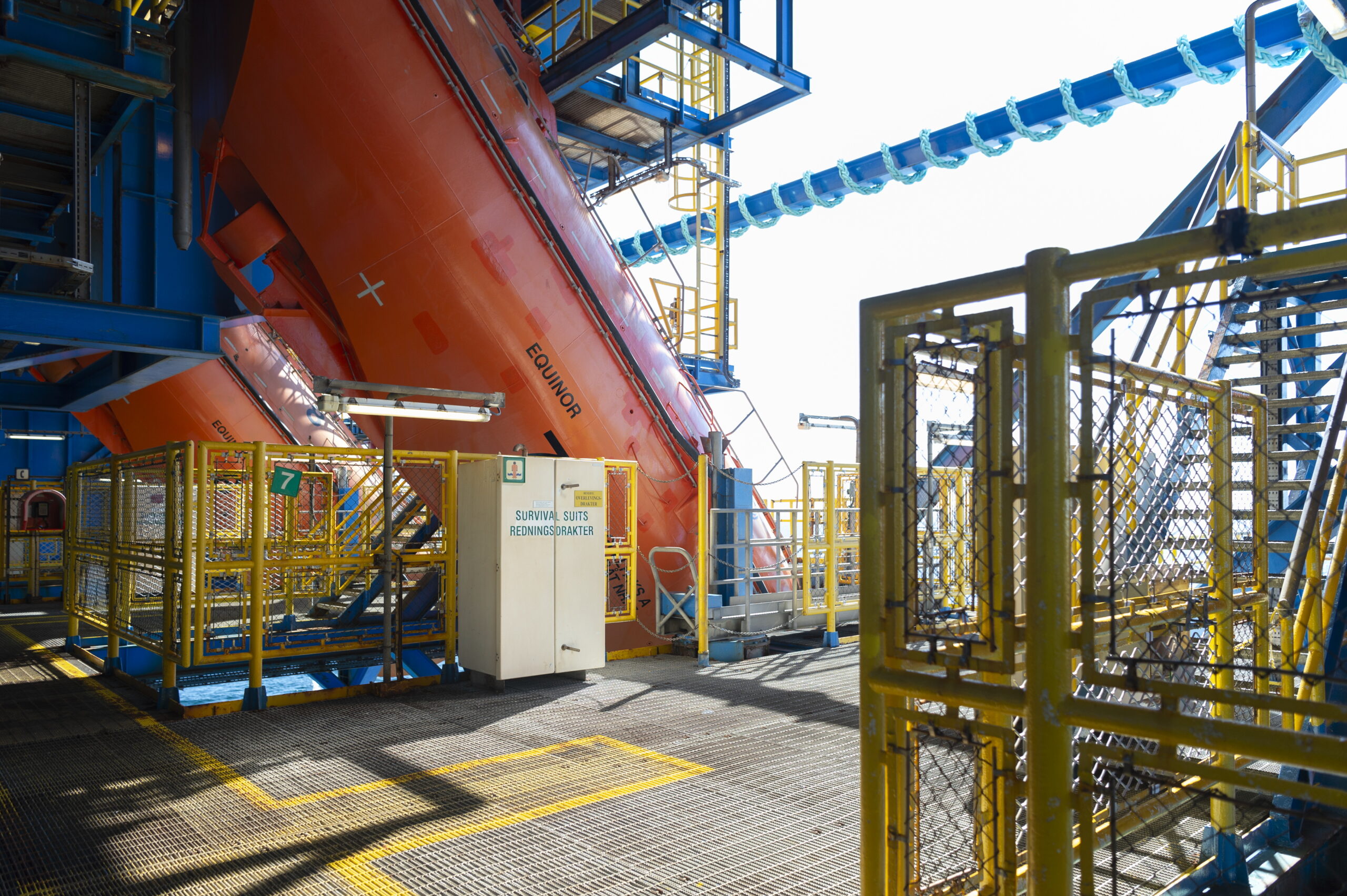
3. Lifeboat Area
Beneath the accommodation module on the west side are eight of the platform’s ten lifeboats. The lifeboat deck spans the full deck frame and sits approximately 30 meters above sea level. Two emergency chutes are installed here, which can deploy rafts. Due to the platform’s size (167.7 meters from east to west), there are also two free-fall lifeboats and two raft stations on the east side to ensure fast evacuation from all areas.
4. Water Shaft
Located beneath the accommodation module, the western shaft is filled with water. In addition to contributing to buoyancy, its primary function is to supply water for firefighting and daily use on the platform.
Processing and Support Functions (Middle)
The central section of the platform contains the main processing plant and various support systems such as cranes, turbines, and technical modules for separation and power generation.
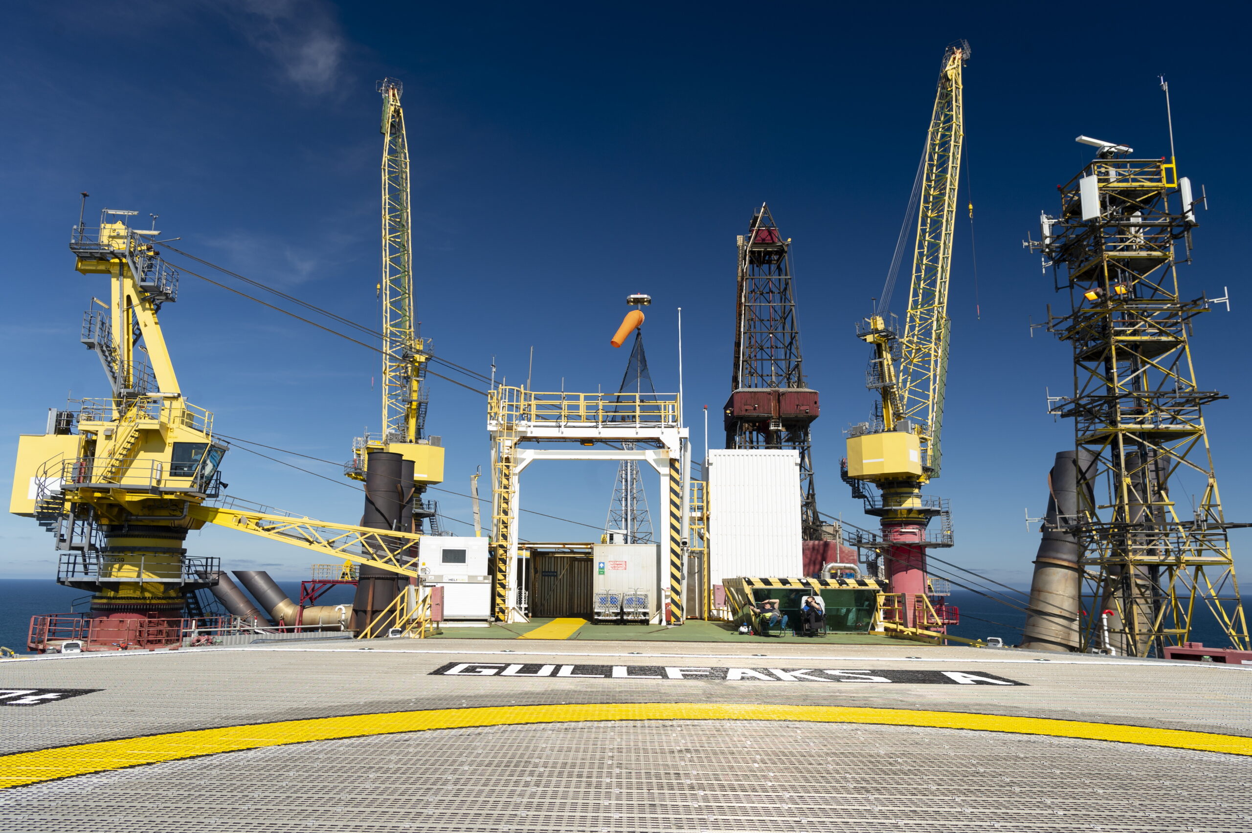
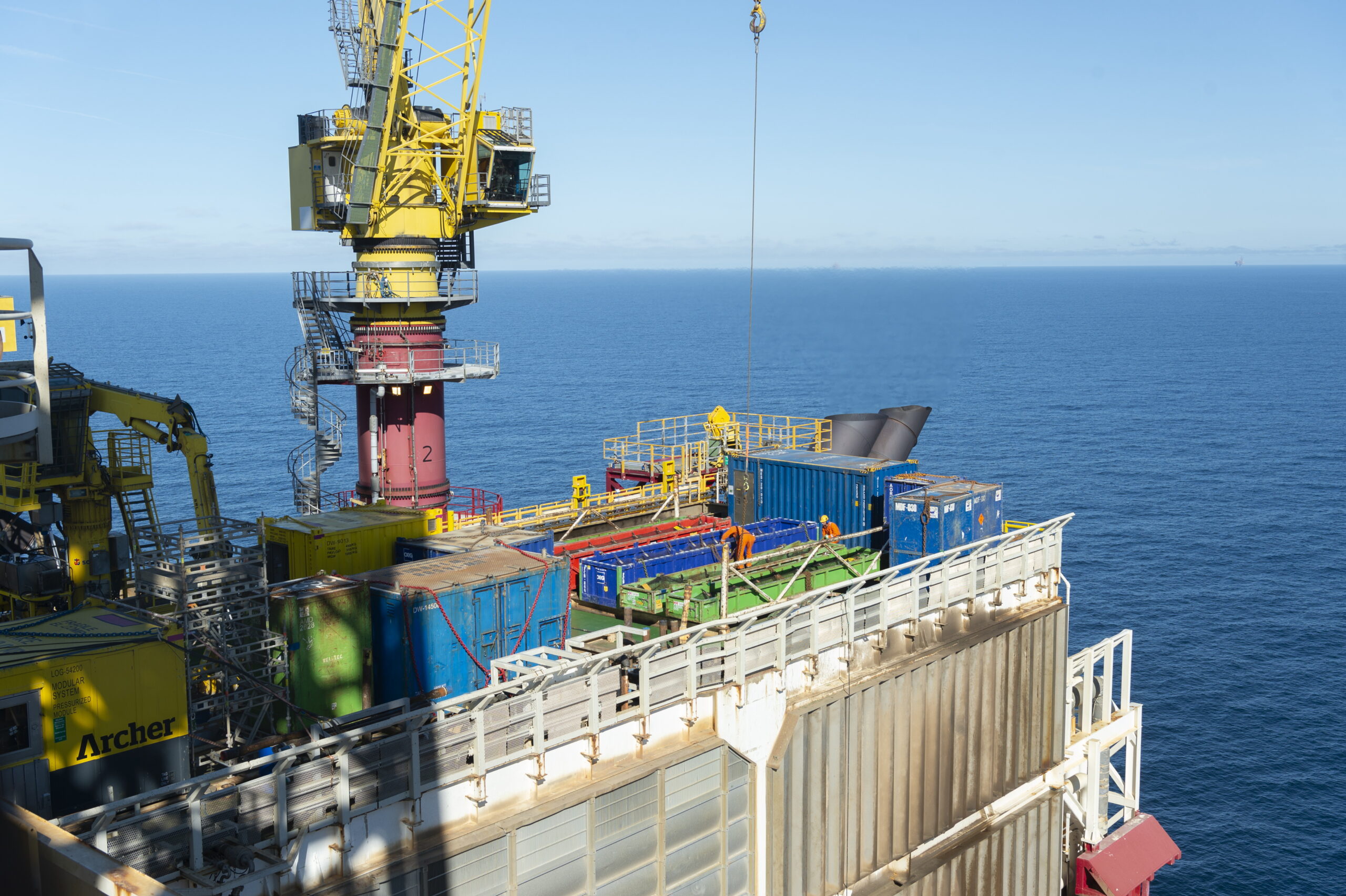
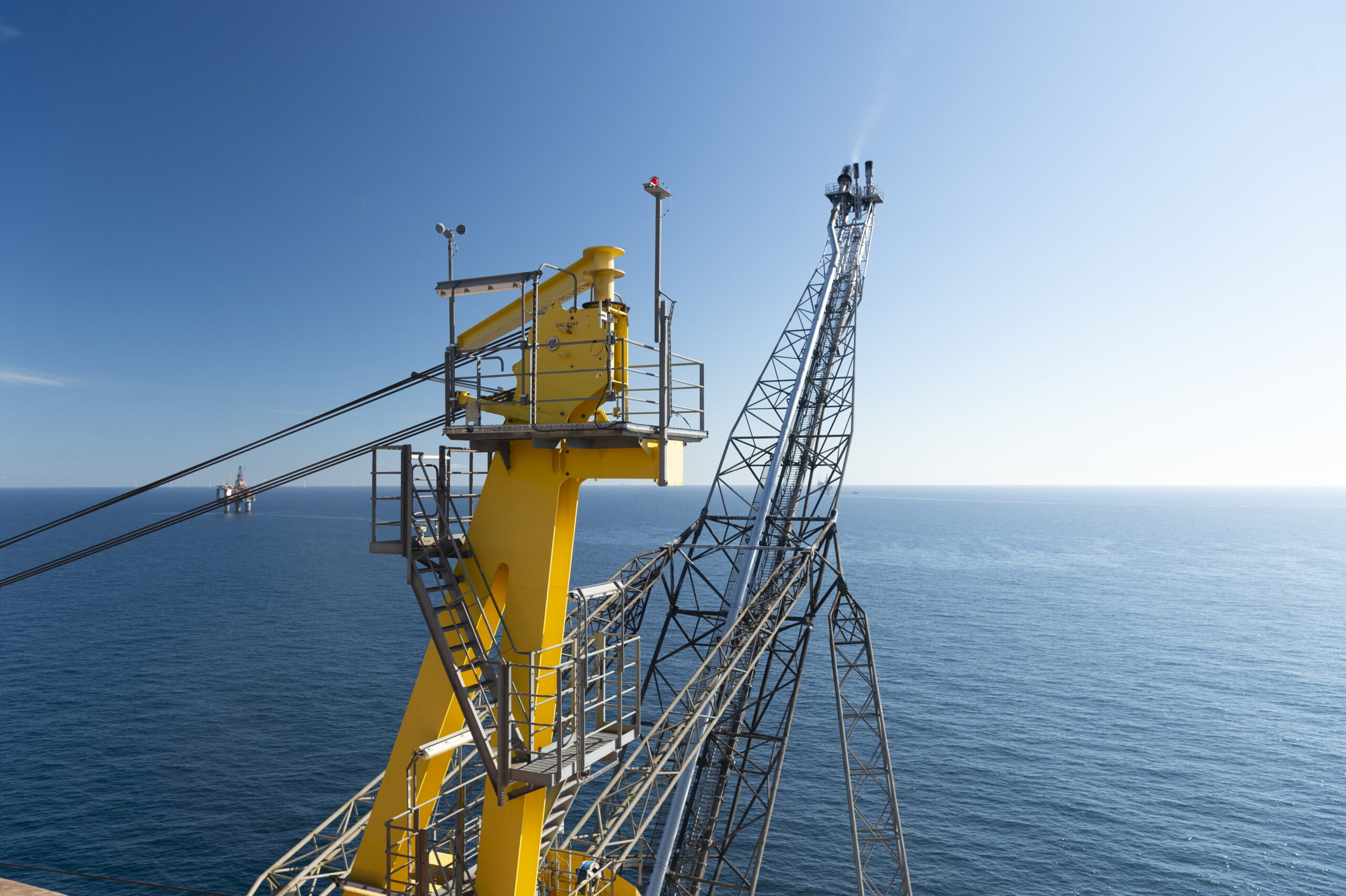
5. Cranes and Cargo Deck
The uppermost deck, above the process plant and turbines, is known as the weather deck. It is used for receiving cargo. Gullfaks A is equipped with four cranes: two on the north side and two on the south side.
6. Turbines
Large pipes visible at the top of the platform carry heat from the gas turbines. Gullfaks A has six gas turbines that meet much of its energy demand. There is also a backup turbine powered by diesel. The platform also receives electricity from the Hywind Tampen wind farm, reducing turbine usage.
7. Separation Facility
The platform features a sophisticated separation system to split oil, gas, and water. The first-stage separator is located on the 1st floor, while the second- and third-stage separators are on the 4th floor. Water is treated before discharge, gas is piped to shore, and oil is sent to storage cells at the platform base. In 1996, during the development of Gullfaks Sør, the platform received new modules for increased gas processing and reinjection.
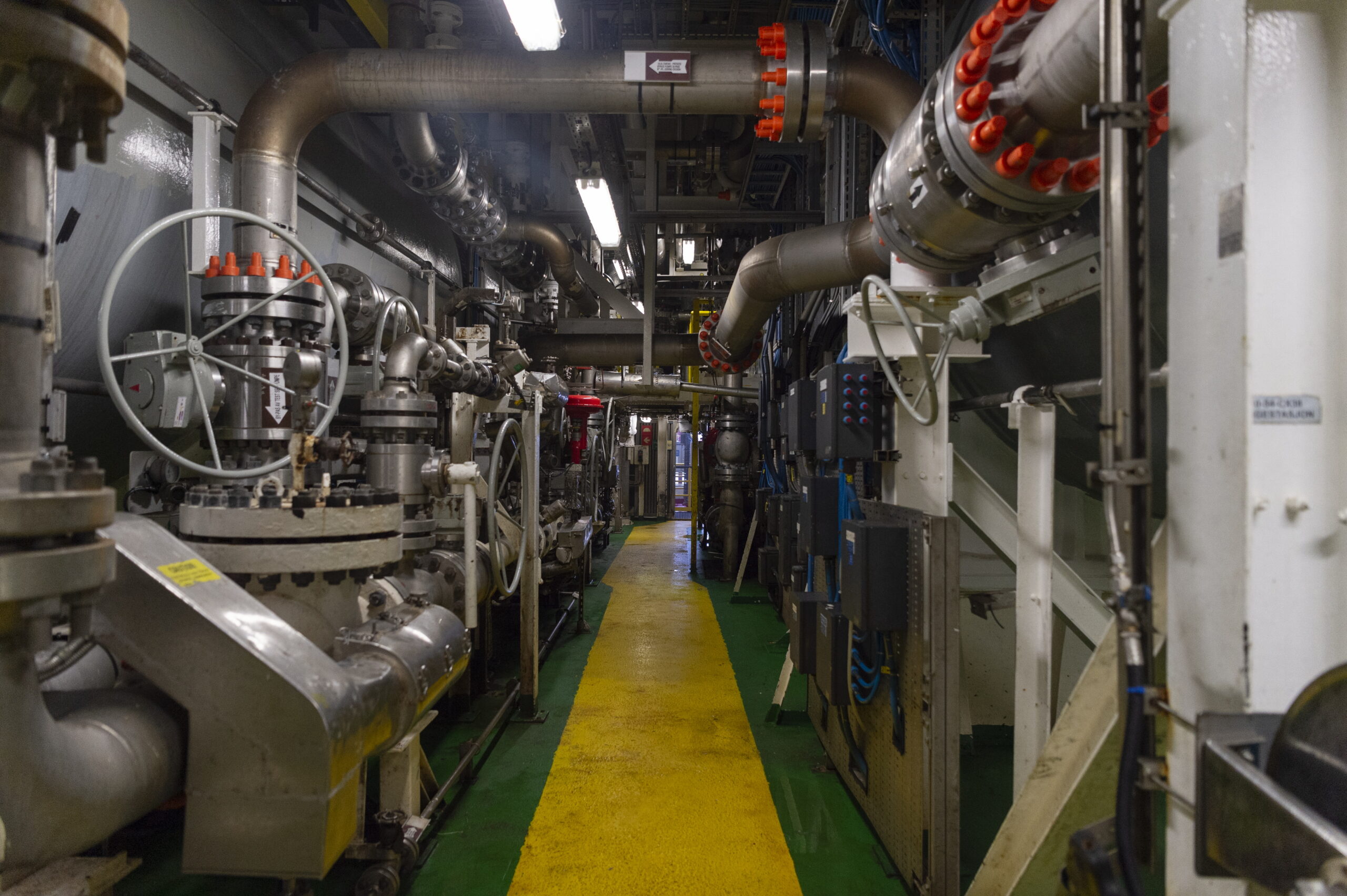
8. Utility Shaft
The utility shaft is the central one of the platform’s four shafts. Oil is routed down through this shaft to the storage cells. To prevent buoyancy, the cells are always filled with liquid. Any gas not separated out is rerouted to the flare system.
Drilling and Wells (East)
On the eastern side are the drilling and well areas, including the derrick, well modules, drilling shafts, and flare system—the core of production operations.
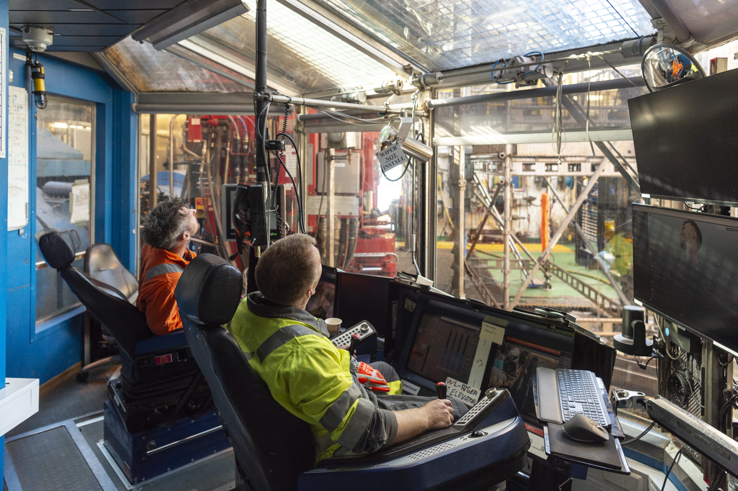
9. Derrick
The tallest structure on the platform, the derrick stands 135 meters above sea level. The tower itself is 55 meters tall and is used to vertically stack large sections of drill pipe. Drilling is controlled from a room at the base of the tower. The derrick can be moved between the northern and southern parts of the platform via winches.
10. The Flare Boom
At the far east end of the platform is the flare boom. It is used to burn excess gas when necessary, preventing gas from drifting toward the rest of the platform and creating a fire hazard. The flare can be ignited from, among other places, the control room and the lifeboat deck, but it is usually turned off.
11. Well Modules
These extend across all floors on the platform’s east side. Here, oil and gas rise from production wells, while fluids are injected into the reservoir through injection wells.
12. Drilling Shafts
The platform is designed to support up to 48 wells at once—24 on the south side and 24 on the north. Pipes descend to the seabed through one of the two drilling shafts. The derrick cannot cover both shafts simultaneously but can be moved between them.
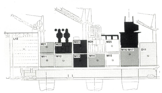
Overview: Module by Module, Floor by Floor
The diagram shows the module layout. It dates from 1983, prior to installation.[REMOVE]Fotnote: Status – Internal newsletter for Statoil employees. (1983). No. 16, p. 10. The basic structure remains the same today.